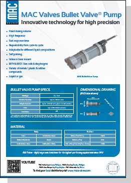
I know it is much larger than I need since the MAC valve I am controlling only pulls 5.4 watts and the MOSFET is rated for 30 amps. The MOSFET I chose is the FQP30N60L and chose that just because I have a lot of them from some of my Arduino projects and the fact that it works at logic level. Is this an acceptable choice in an automotive environment? I used a 7805 for the 5v regulator due to its popularity. So these are the questions/concerns I have. Down the road I would like to change this from an open loop to a closed loop setup and swap out the 555 for an Arduino and add a MAP sensor to read a value in and use a PID loop to actually target a boost pressure and not just a duty cycle. So although they say 'if its not broke dont fix it' I would like to learn from my design mistakes and try to build a better device. I have soldered this together on a breadboard and have it running in my S10 and have not ran into any issues yet. I have the valve running at around 20Hz and with a 100k POT I can adjust the duty cycle from about 6-88% which is outside of the effective range that the valve actual functions (~14-78%). Basically to see if there is something I missed or obvious that I should change or should have designed differently. I have some questions and wanted to get feedback on this circuit I have put together.


